Zero to ESP32 remote control
Published on
A learn in public post on building a multi-button remote control with ESP32, esphome and Home Assistant.
Background #
I had a pair of shelf speakers some time ago. They were plugged in and turned on all the time and a brown-out fried them. I tried my hand at repairing them, but having next to zero skills when it comes to working with stuff in the meatspace, I probably just broke them even further, or at least beyond economic repair.
Since then I was looking for opportunities to improve my hardware skills, so my next screw up will be less spectacular.
NB: I don’t consider myself even remotely experienced to give the advice on the “this is how this should be done” level. I wrote this post to remember the lessons learned and because I wish something like this existed in one place when I was starting out.
Project goals #
The main goal here is to practice and to build something actually useful. The “useful” part is:
- A button to turn on/off the office lights. My office is pretty dark and I need some back light for video calls
- A button to send wake-on-lan packet to my workstation in the rack
- A button to switch inputs to the KVM installed behind my work desk
All three buttons will report their state to home assistant. The KVM I have uses a 3.5mm button which works as a momentary switch. The “switch inputs” bit will work as a momentary switch. One of the pins of ESP32 will connect to an optocoupler which will in turn pretend to be the original KVM button.
Hardware #
Tools #
These are tools that I (now) have in the toolbox and some comments on them.
If provided, none of the links are affiliate.
- Soldering iron:
YUHUA 939D+. Before purchasing it, I had a no-name bargain-bin soldering iron. While not on the level of more professional irons, it seems to be pretty capable. - Project mat: a decently (~53 x 35 cm) sized silicone project mat to keep everything in place and protect the worktable from solder
- Helping hands: I am using a pair of helping hands like these. They’re not entirely awful, but I wish I had something better suited for holding a PCB in place like a vise or a set of stand-offs
- Solder: I went with Weller WSW SnPb (T0051403299). It’s lead-based which is a downside, but my workspace is well-ventilated so it’s not too much of a problem.
- A set of breadboards
- Dupont jumpers
- Wire stripper and cutter: make sure to get something that can work with >= 20 gauge for smaller wires
- Straight cutters
- Eye protection. Safety squints can only get one so far when bits start flying all over the place.
- ESD pliers
- Multimeter: procured from the same no-name bargain bin as the original soldering iron, it worked fine for simple continuity tests and checking the voltage drops. I will continue using it for now, but will probably get something less sketchy and with a proper safety category.
- Desoldering wick: for fixing the inevitable mistakes.
- Desoldering pump: for fixing the inevitable big mistakes.
Materials for the circuit #
- ESP32: I purchased a set of 3 ESP32 development kits and a couple more to try out different configurations. At this stage this is more than enough, but I will probably get a different one when going into “production”.
- A perf board: just a standard one.
- Bell wire: I had a spool of 20 gauge wire left over from another project. In hindsight, I should have probably used a smaller wire in some areas. 20 gauge wire was a bit hard to bend to the exact shape that I wanted. It did work well for straight “bus” runs. I will probably switch to 24 AWG tinned copper in future.
- Buttons
- Resistors:
- 10k Ohm resistor as a pull-up
- 10k Ohm, 22k Ohm and 47k Ohm for buttons
- 220 Ohm for the optocoupler LED
- Optocoupler:
PC817 - 3.5mm jack breakout board
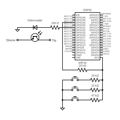
The circuit #
Rough idea is to use a single ESP32 pin (GPIO34) as ADC input. It’s
connected to 3v3 via a pull-up resistor so that when no buttons are pressed,
reading will be ~3 volts.
Each button has a resistor in series with values chosen so that so that ADC can see any combination of buttons pressed. E.g.:
- Pressing just one button drops the voltage to 2.73
- Pressing first and third button: 1.99
- Pressing only the third button: 2.28
For toggling the KVM switch, I used an optocoupler with a 220 Ohm resistor
connected to GPIO32. I chose this pin because it can function as an output
(unlike, say, GPIO35).
The connection is:
GPIO32to 220 Ohm to anode- Cathode to ground
- Collector to tip
- Emitter to sleeve
Schematically (courtesy of circuit-diagram.org):
And here it is, in its janky glory:
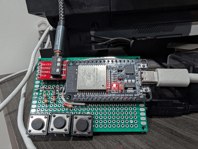
Having always been fascinated with the blinkenlights, I dub thee “das Schaltenknopken 1.0”.
The optocoupler is hiding below the 3.5mm breakout board, the wire going to the top connects to the KVM switch. Pin and ground connections for the optocoupler are below the perfboard.
This is by no means a final version, but I wanted something less bulky than a breadboard on my table.
Software #
The main logic (“if button 1 is pressed, do the thing”) is implemented in Home Assistant and is trivial. The relevant bits of esphome configuration:
sensor:
  # This sensor will report voltage on the pin and the binary_sensor's will calculate which button is actually pressed
  - platform: adc
    pin: GPIO34
    id: voltage_ladder
    update_interval: 0.1s
    internal: true
    attenuation: 11db # range is  up to 3.3 => needs 11db attenuation
    filters:
      # Apply a debouncing filter. The value will only update
      # after the voltage has been stable for 50ms.
      - debounce: 50ms

binary_sensor:
  # The binary sensors will report the state of the buttons
  # Empirical voltage values:
  # # 1 solo: 2.73
  # 1+2: 1.51
  # 1+2+3: 1.25
  # 1+3: 1.99
  # 2 solo: 1.67
  # 2+3: 1.36
  # 3 solo: 2.28
  # The lambdas will check if the value is within a ~0.2 neighborhood of the value above

  # Button 1 (leftmost)
  - platform: template
    name: "Button 1"
    id: button_1
    # not specifying on_press, that code is managed through nix
    lambda: |-
      float voltage = id(voltage_ladder).state;
      // Solo
      // 1+2
      // 1+3
      // 1+2+3
      return (voltage >= 2.72 && voltage <= 2.745) ||
             (voltage >= 1.50 && voltage <= 1.52) ||
             (voltage >= 1.98 && voltage <= 2.00) ||
             (voltage >= 1.24 && voltage <= 1.26);

  # Button 2 (middle)
  - platform: template
    name: "Button 2"
    id: button_2
    # not specifying on_press, that code is managed through nix
    lambda: |-
      float voltage = id(voltage_ladder).state;
      // Solo
      // 1+2
      // 2+3
      // 1+2+3
      return (voltage >= 1.655 && voltage <= 1.685) ||
             (voltage >= 1.50 && voltage <= 1.52) ||
             (voltage >= 1.35 && voltage <= 1.37) ||
             (voltage >= 1.24 && voltage <= 1.26);

  # Button 3 (right)
  - platform: template
    name: "Button 3"
    id: button_3
    # not specifying on_press, that code is managed through nix
    lambda: |-
      float voltage = id(voltage_ladder).state;
      // Solo
      // 1+3
      // 2+3
      // 1+2+3
      return (voltage >= 2.265 && voltage <= 2.295) ||
             (voltage >= 1.98 && voltage <= 2.00) ||
             (voltage >= 1.35 && voltage <= 1.37) ||
             (voltage >= 1.24 && voltage <= 1.26);

output:
  - platform: gpio
    pin: 32
    id: kvm_press_output

button:
  - platform: template
    name: "KVM Switch Button"
    on_press:
      - output.turn_on: kvm_press_output
      - delay: 200ms
      - output.turn_off: kvm_press_output
Miscellaneous notes #
- As an alternative to the optocoupler I could probably use a relay, but optocouplers are not mechanical and perfectly suitable for a project like this.
- Buy more ESP32s than you think you need. It’s helpful to keep a copy of the circuit I was building on a breadboard.
- Use multimeter continuity mode on janky joints to make sure that it actually works.
- With the materials above, solder flows fine at ~590 Fahrenheit. The Weller solder has flux core, so no extra flux is necessary.
- Soldering sequence that worked to get decent joins: use chisel tip to touch the pad and the component for 1-2 seconds, touch with solder, remove solder, wait 1 second, remove the iron.
esphomeneeds some out of band configuration on NixOS: nixpkgs issue, my config.- Because of the choice of wire, I had to solder some ESP32 legs directly to the wires a few mm away below the perf board. While fine for the time being, smaller wire and tying it to the leg before soldering would had been better.
Future #
Longer-term I am planning to install this project under my main monitor that has USB ports on the bottom side. The display will provide power and the cable going to the KVM will be tucked away behind the monitor. Since I am using only a couple of pins, I can switch to a small version of ESP32 to save on space. The whole board can be in a tiny 3d-printed enclosure.